|
upm
1.7.1
Sensor/Actuator repository for libmraa (v2.0.0)
|
|
upm
1.7.1
Sensor/Actuator repository for libmraa (v2.0.0)
|
L3GD20 Tri-axis Digital Gyroscope API. More...
The L3GD20 The L3GD20 is a low-power three-axis angular rate sensor. This driver supports IIO and I2C modes. Some methods will only work in one mode or the other. See the documentation on the methods to determine whether a given method is operation in a given mode. Both the I2C and IIO mechanisms make use of the calibration and denoise algorithms.
For I2C mode, not all capabilities of the device are supported, but a complete register map and low level read/write methods are provided to add any missing functionality.
Example using IIO
Example using I2C
Data Structures | |
| struct | filter_median_t |
| struct | gyro_cal_t |
Public Types | |
| enum | L3GD20_REGS_T { REG_WHO_AM_I = 0x0f, REG_CTRL_REG1 = 0x20, REG_CTRL_REG2 = 0x21, REG_CTRL_REG3 = 0x22, REG_CTRL_REG4 = 0x23, REG_CTRL_REG5 = 0x24, REG_REFERENCE = 0x25, REG_OUT_TEMPERATURE = 0x26, REG_STATUS_REG = 0x27, REG_OUT_X_L = 0x28, REG_OUT_X_H = 0x29, REG_OUT_Y_L = 0x2a, REG_OUT_Y_H = 0x2b, REG_OUT_Z_L = 0x2c, REG_OUT_Z_H = 0x2d, REG_FIFO_CTRL_REG = 0x2e, REG_FIFO_SRC_REG = 0x2f, REG_INT1_CFG = 0x30, REG_INT1_SRC = 0x31, REG_INT1_TSH_XH = 0x32, REG_INT1_TSH_XL = 0x33, REG_INT1_TSH_YH = 0x34, REG_INT1_TSH_YL = 0x35, REG_INT1_TSH_ZH = 0x36, REG_INT1_TSH_ZL = 0x37, REG_INT1_DURATION = 0x38 } |
| enum | CTRL_REG1_BITS_T { CTRL_REG1_YEN = 0x01, CTRL_REG1_XEN = 0x02, CTRL_REG1_ZEN = 0x04, CTRL_REG1_PD = 0x08, CTRL_REG1_BW0 = 0x10, CTRL_REG1_BW1 = 0x20, _CTRL_REG1_BW_MASK = 3, _CTRL_REG1_BW_SHIFT = 4, CTRL_REG1_DR0 = 0x40, CTRL_REG1_DR1 = 0x80, _CTRL_REG1_DR_MASK = 3, _CTRL_REG1_DR_SHIFT = 6, _CTRL_REG1_ODR_CUTOFF0 = 0x10, _CTRL_REG1_ODR_CUTOFF1 = 0x20, _CTRL_REG1_ODR_CUTOFF2 = 0x40, _CTRL_REG1_ODR_CUTOFF3 = 0x80, _CTRL_REG1_ODR_CUTOFF_MASK = 15, _CTRL_REG1_ODR_CUTOFF_SHIFT = 4 } |
| enum | ODR_CUTOFF_T { ODR_CUTOFF_95_12_5 = 0, ODR_CUTOFF_95_25 = 1, ODR_CUTOFF_190_12_5 = 4, ODR_CUTOFF_190_25 = 5, ODR_CUTOFF_190_50 = 6, ODR_CUTOFF_190_70 = 7, ODR_CUTOFF_380_20 = 8, ODR_CUTOFF_380_25 = 9, ODR_CUTOFF_380_50 = 10, ODR_CUTOFF_380_100 = 11, ODR_CUTOFF_760_30 = 12, ODR_CUTOFF_760_35 = 13, ODR_CUTOFF_760_50 = 14, ODR_CUTOFF_760_100 = 15 } |
| enum | POWER_MODES_T { POWER_DOWN, POWER_SLEEP, POWER_NORMAL } |
| enum | CTRL_REG2_BITS_T { _CTRL_REG2_RESERVED_BITS = 0x40 | 0x80, CTRL_REG2_HPCF0 = 0x01, CTRL_REG2_HPCF1 = 0x02, CTRL_REG2_HPCF2 = 0x04, CTRL_REG2_HPCF3 = 0x08, _CTRL_REG2_HPCF_MASK = 15, _CTRL_REG2_HPCF_SHIFT = 0, CTRL_REG2_HPM0 = 0x10, CTRL_REG2_HPM1 = 0x20, _CTRL_REG2_HPM_MASK = 3, _CTRL_REG2_HPM_SHIFT = 4 } |
| enum | HPCF_T { HPCF_7_2 = 0, HPCF_3_5 = 1, HPCF_1_8 = 2, HPCF_0_9 = 3, HPCF_0_45 = 4, HPCF_0_18 = 5, HPCF_0_09 = 6, HPCF_0_045 = 7, HPCF_0_018 = 8, HPCF_0_009 = 9 } |
| enum | HPM_T { HPM_NORMAL_RESET_FILTER = 0, HPM_REFERENCE_SIGNAL = 1, HPM_NORMAL = 2, HPM_AUTORESET_ON_INT = 3 } |
| enum | CTRL_REG3_BITS_T { CTRL_REG3_I2_EMPTY = 0x01, CTRL_REG3_I2_ORUN = 0x02, CTRL_REG3_I2_WTM = 0x04, CTRL_REG3_I2_DRDY = 0x08, CTRL_REG3_PP_OD = 0x10, CTRL_REG3_H_LACTIVE = 0x20, CTRL_REG3_I1_BOOT = 0x40, CTRL_REG3_I1_INT1 = 0x80 } |
| enum | CTRL_REG4_BITS_T { _CTRL_REG4_RESERVED_BITS = 0x02 | 0x04 | 0x08, CTRL_REG4_SIM = 0x01, CTRL_REG4_FS0 = 0x10, CTRL_REG4_FS1 = 0x20, _CTRL_REG4_FS_MASK = 3, _CTRL_REG4_FS_SHIFT = 4, CTRL_REG4_BLE = 0x40, CTRL_REG4_BDU = 0x80 } |
| enum | FS_T { FS_250 = 0, FS_500 = 1, FS_2000 = 2 } |
| enum | CTRL_REG5_BITS_T { _CTRL_REG5_RESERVED_BITS = 0x20, CTRL_REG5_OUT_SEL0 = 0x01, CTRL_REG5_OUT_SEL1 = 0x02, _CTRL_REG5_OUT_SEL_MASK = 3, _CTRL_REG5_OUT_SEL_SHIFT = 0, CTRL_REG5_INT1_SEL0 = 0x04, CTRL_REG5_INT1_SEL1 = 0x08, _CTRL_REG5_INT1_SEL_MASK = 3, _CTRL_REG5_INT1_SEL_SHIFT = 2, CTRL_REG5_HPEN = 0x10, CTRL_REG5_FIFO_EN = 0x40, CTRL_REG5_BOOT = 0x80 } |
| enum | STATUS_REG_BITS_T { STATUS_REG_XDA = 0x01, STATUS_REG_YDA = 0x02, STATUS_REG_ZDA = 0x04, STATUS_REG_ZYXDA = 0x08, STATUS_REG_XOR = 0x10, STATUS_REG_YOR = 0x20, STATUS_REG_ZOR = 0x40, STATUS_REG_ZYXOR = 0x80 } |
| enum | FIFO_CTRL_REG_BITS_T { FIFO_CTRL_REG_WTM0 = 0x01, FIFO_CTRL_REG_WTM1 = 0x02, FIFO_CTRL_REG_WTM2 = 0x04, FIFO_CTRL_REG_WTM3 = 0x08, FIFO_CTRL_REG_WTM4 = 0x10, _FIFO_CTRL_REG_WTM_MASK = 31, _FIFO_CTRL_REG_WTM_SHIFT = 0, FIFO_CTRL_REG_FM0 = 0x20, FIFO_CTRL_REG_FM1 = 0x40, FIFO_CTRL_REG_FM2 = 0x80, _FIFO_CTRL_REG_FM_MASK = 7, _FIFO_CTRL_REG_FM_SHIFT = 5 } |
| enum | FIFO_MODE_T { FIFO_MODE_BYPASS = 0, FIFO_MODE_FIFO = 1, FIFO_MODE_STREAM = 2, FIFO_MODE_STREAM_TO_FIFO = 3, FIFO_MODE_BYPASS_TO_STREAM = 4 } |
| enum | FIFO_SRC_BITS_T { FIFO_SRC_REG_FSS0 = 0x01, FIFO_SRC_REG_FSS1 = 0x02, FIFO_SRC_REG_FSS2 = 0x04, FIFO_SRC_REG_FSS3 = 0x08, FIFO_SRC_REG_FSS4 = 0x10, _FIFO_SRC_REG_FSS_MASK = 31, _FIFO_SRC_REG_FSS_SHIFT = 0, FIFO_SRC_REG_EMPTY = 0x20, FIFO_SRC_REG_OVRN = 0x40, FIFO_SRC_REG_WTM = 0x80 } |
| enum | INT1_CFG_BITS_T { INT1_CFG_XLIE = 0x01, INT1_CFG_XHIE = 0x02, INT1_CFG_YLIE = 0x04, INT1_CFG_YHIE = 0x08, INT1_CFG_ZLIE = 0x10, INT1_CFG_ZHIE = 0x20, INT1_CFG_LIR = 0x40, INT1_CFG_AND_OR = 0x80 } |
| enum | INT1_SRC_BITS_T { _INT1_SRC_RESERVED_BITS = 0x80, INT1_SRC_XL = 0x01, INT1_SRC_XH = 0x02, INT1_SRC_YL = 0x04, INT1_SRC_YH = 0x08, INT1_SRC_ZL = 0x10, INT1_SRC_ZH = 0x20, INT1_SRC_IA = 0x40 } |
| enum | INT1_DURATION_BITS_T { INT1_DURATION_D0 = 0x01, INT1_DURATION_D1 = 0x02, INT1_DURATION_D2 = 0x04, INT1_DURATION_D3 = 0x08, INT1_DURATION_D4 = 0x10, INT1_DURATION_D5 = 0x20, INT1_DURATION_D6 = 0x40, INT1_DURATION_WAIT = 0x80 } |
Public Member Functions | |
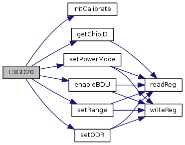
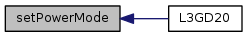
| L3GD20 (int device) | |
| L3GD20 (int bus, int addr) | |
| ~L3GD20 () | |
| uint8_t | getChipID () |
| void | getGyroscope (float *x, float *y, float *z) |
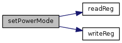
| void | setPowerMode (POWER_MODES_T mode) |
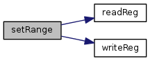
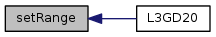
| void | setRange (FS_T range) |
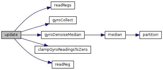
| void | update () |
| float | getTemperature (bool fahrenheit=false) |
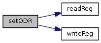
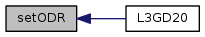
| void | setODR (ODR_CUTOFF_T odr) |
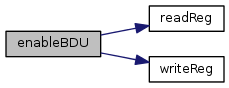
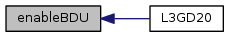
| void | enableBDU (bool enable) |
| uint8_t | getStatusBits () |
| void | installISR (void(*isr)(char *, void *), void *arg) |
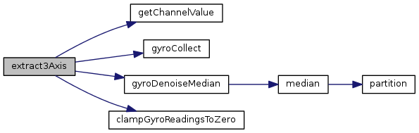
| int64_t | getChannelValue (unsigned char *input, mraa_iio_channel *chan) |
| bool | enableBuffer (int length) |
| bool | disableBuffer () |
| bool | setScale (const float scale) |
| bool | setSamplingFrequency (const float sampling_frequency) |
| bool | enable3AxisChannel () |
| bool | extract3Axis (char *data, float *x, float *y, float *z) |
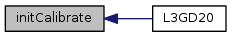
| void | initCalibrate () |
| bool | getCalibratedStatus () |
| void | getCalibratedData (float *bias_x, float *bias_y, float *bias_z) |
| void | loadCalibratedData (float bias_x, float bias_y, float bias_z) |
| uint8_t | readReg (uint8_t reg) |
| int | readRegs (uint8_t reg, uint8_t *buffer, int len) |
| void | writeReg (uint8_t reg, uint8_t val) |
| bool | gyroCollect (float x, float y, float z) |
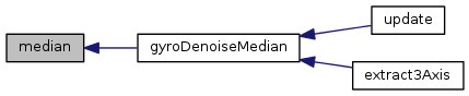
| void | gyroDenoiseMedian (float *x, float *y, float *z) |
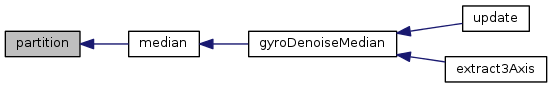
| float | median (float *queue, unsigned int size) |
| unsigned int | partition (float *list, unsigned int left, unsigned int right, unsigned int pivot_index) |
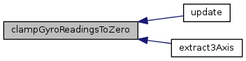
| void | clampGyroReadingsToZero (float *x, float *y, float *z) |
Protected Attributes | |
| mraa::I2c * | m_i2c |
| float | m_gyrScale |
| float | m_gyrX |
| float | m_gyrY |
| float | m_gyrZ |
| float | m_temperature |
| enum L3GD20_REGS_T |
L3GD20 registers (i2c)
| enum CTRL_REG1_BITS_T |
CTRL_REG1 bits
| enum ODR_CUTOFF_T |
CTRL_REG1_ODR_CUTOFF values
| enum POWER_MODES_T |
CTRL_REG1 power modes. Power is controlled via the PD, Zen, Yen, and Xen bitfields.
| enum CTRL_REG2_BITS_T |
CTRL_REG2 bits
| enum HPCF_T |
CTRL_REG2_HPCF values (see table 26 in the datasheet)
| enum HPM_T |
CTRL_REG2_HPM values
| enum CTRL_REG3_BITS_T |
CTRL_REG3 bits
| enum CTRL_REG4_BITS_T |
CTRL_REG4 bits
| enum FS_T |
CTRL_REG4_FS values
| enum CTRL_REG5_BITS_T |
CTRL_REG5 bits
| enum STATUS_REG_BITS_T |
STATUS_REG bits
| enum FIFO_CTRL_REG_BITS_T |
FIFO_CTRL_REG bits
| enum FIFO_MODE_T |
FIFO_CTRL_REG_FM (FIFO mode) values
| enum FIFO_SRC_BITS_T |
FIFO_SRC_REG bits
| enum INT1_CFG_BITS_T |
INT1_CFG bits
| enum INT1_SRC_BITS_T |
INT1_SRC bits
| enum INT1_DURATION_BITS_T |
INT1_DURATION bits
| L3GD20 | ( | int | device | ) |
L3GD20 Tri-axis Digital Gyroscope Contructor for IIO operation
| device | iio device number |

| L3GD20 | ( | int | bus, |
| int | addr | ||
| ) |
L3GD20 Tri-axis Digital Gyroscope Contructor for I2C operation
| bus | i2c bus |
| addr | I2C address |
| uint8_t getChipID | ( | ) |
Return the chip ID. I2C only.


| void getGyroscope | ( | float * | x, |
| float * | y, | ||
| float * | z | ||
| ) |
Return gyroscope data in radians per second. update() must have been called prior to calling this method. I2C only.
| x | Pointer to a floating point value that will have the current x component placed into it. |
| y | Pointer to a floating point value that will have the current y component placed into it. |
| z | Pointer to a floating point value that will have the current z component placed into it. |
| void setPowerMode | ( | POWER_MODES_T | mode | ) |
Set the power mode of the device. I2C only.
| mode | One of the POWER_MODES_T values. |
| void setRange | ( | FS_T | range | ) |
Set the gyroscope detection scaling range. This device supports 250, 500 and 2000 degree/s ranges. I2C only.
| range | One of the FS_T values. |
| void update | ( | void | ) |
Update the internal stored values from sensor data. This method must be called before querying any data (getTemperature() and getGyroscope()). I2C only.
| float getTemperature | ( | bool | fahrenheit = false | ) |
Return the current measured temperature. Note, this is not ambient temperature. update() must have been called prior to calling this method. I2C only.
| fahrenheit | true to return data in Fahrenheit, false for Celicus. Celsius is the default. |
| void setODR | ( | ODR_CUTOFF_T | odr | ) |
Set the output data rate and cut off frequency of the device. I2C only.
| odr | One of the ODR_CUTOFF_T values. |
| void enableBDU | ( | bool | enable | ) |
Enable or disable Block Data Update. When enabled, this ensures that LSB's or MSB's of a given axis are not being updated while the other is being read. This is enabled by default. I2C only.
| enable | true to enable, false to disable |
| uint8_t getStatusBits | ( | ) |
Return the bitfields of the Status register. This register provides information on the status of data gathering. I2C only.

| void installISR | ( | void(*)(char *, void *) | isr, |
| void * | arg | ||
| ) |
Installs an interrupt service routine (ISR) to be called when an interrupt occurs. IIO only.
| isr | Pointer to a function to be called on interrupt |
| arg | Pointer to an object to be supplied as an argument to the ISR. |
| int64_t getChannelValue | ( | unsigned char * | input, |
| mraa_iio_channel * | chan | ||
| ) |
Extract the channel value based on channel type. IIO only.
| input | Channel data |
| chan | MRAA iio-layer channel info |

| bool enableBuffer | ( | int | length | ) |
Enable trigger buffer. IIO only.
| length | buffer length in integer |
| bool disableBuffer | ( | ) |
Disable trigger buffer. IIO only.
| bool setScale | ( | const float | scale | ) |
Set scale. IIO only. For I2C operation, use setRange() with the appropriate FS_T value.
| scale | in float Available scales are 0.000153(250dps), 0.000305(500dps), and 0.001222(2000dps) Default scale is 0.000153 |
| bool setSamplingFrequency | ( | const float | sampling_frequency | ) |
Set sampling frequency. IIO only. For I2C operation, use the setODR() method with the appropriate ODR_CUTOFF_T value.
| sampling_frequency | sampling frequency in float Available sampling frequency are 95, 190, 380, and 760 Default sampling frequency is 95 |
| bool enable3AxisChannel | ( | ) |
Enable 3 axis scan element. IIO only.
| bool extract3Axis | ( | char * | data, |
| float * | x, | ||
| float * | y, | ||
| float * | z | ||
| ) |
Process enabled channel buffer and return x, y, z axis. IIO only.
| data | Enabled channel data, 6 bytes, each axis 2 bytes |
| x | X-Axis |
| y | Y-Axis |
| z | Z-Axis |
| void initCalibrate | ( | ) |
Reset calibration data and start collect calibration data again
| bool getCalibratedStatus | ( | ) |
Get calibrated status, return true if calibrate successfully
| void getCalibratedData | ( | float * | bias_x, |
| float * | bias_y, | ||
| float * | bias_z | ||
| ) |
Get calibrated data
| void loadCalibratedData | ( | float | bias_x, |
| float | bias_y, | ||
| float | bias_z | ||
| ) |
Load calibrated data
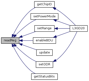
| uint8_t readReg | ( | uint8_t | reg | ) |
Read a register. I2C mode only.
| reg | The register to read. |
| int readRegs | ( | uint8_t | reg, |
| uint8_t * | buffer, | ||
| int | len | ||
| ) |
Read contiguous registers into a buffer. I2C mode only.
| buffer | The buffer to store the results. |
| len | The number of registers to read. |

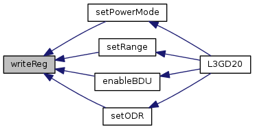
| void writeReg | ( | uint8_t | reg, |
| uint8_t | val | ||
| ) |
Write to a register. I2C mode only.
| reg | The register to write to. |
| val | The value to write. |
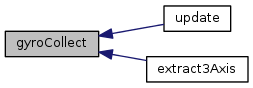
| bool gyroCollect | ( | float | x, |
| float | y, | ||
| float | z | ||
| ) |
Calibrate gyro
| x | X-Axis |
| y | Y-Axis |
| z | Z-Axis |
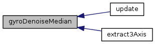
| void gyroDenoiseMedian | ( | float * | x, |
| float * | y, | ||
| float * | z | ||
| ) |
Denoise gyro
| x | X-Axis |
| y | Y-Axis |
| z | Z-Axis |

| float median | ( | float * | queue, |
| unsigned int | size | ||
| ) |
median algorithm
| queue | |
| size |

| unsigned int partition | ( | float * | list, |
| unsigned int | left, | ||
| unsigned int | right, | ||
| unsigned int | pivot_index | ||
| ) |
partition algorithm
| list | |
| left | |
| right | |
| pivot_index |
| void clampGyroReadingsToZero | ( | float * | x, |
| float * | y, | ||
| float * | z | ||
| ) |
Clamp Gyro Readings to Zero
| x | X-Axis |
| y | Y-Axis |
| z | Z-Axis |
 1.8.11

