|
upm
0.8.0
Sensor/Actuator repository for libmraa (v1.1.1)
|
|
upm
0.8.0
Sensor/Actuator repository for libmraa (v1.1.1)
|
API for the BMM150 3-Axis Geomagnetic Sensor. More...
The BMM150 is a standalone geomagnetic sensor for consumer market applications. It allows measurements of the magnetic field in three perpendicular axes. Based on Bosch’s proprietary FlipCore technology, performance and features of BMM150 are carefully tuned and perfectly match the demanding requirements of all 3-axis mobile applications such as electronic compass, navigation or augmented reality.
An evaluation circuitry (ASIC) converts the output of the geomagnetic sensor to digital results which can be read out over the industry standard digital interfaces (SPI and I2C).
Not all functionality of this chip has been implemented in this driver, however all the pieces are present to add any desired functionality. This driver supports both I2C (default) and SPI operation.
This device requires 3.3v operation.
Public Types | |
| enum | BMM150_REGS_T : uint8_t { REG_CHIP_ID = 0x40, REG_MAG_X_LSB = 0x42, REG_MAG_X_MSB = 0x43, REG_MAG_Y_LSB = 0x44, REG_MAG_Y_MSB = 0x45, REG_MAG_Z_LSB = 0x46, REG_MAG_Z_MSB = 0x47, REG_RHALL_LSB = 0x48, REG_RHALL_MSB = 0x49, REG_INT_STATUS = 0x4a, REG_POWER_CTRL = 0x4b, REG_OPMODE = 0x4c, REG_INT_EN = 0x4d, REG_INT_CONFIG = 0x4e, REG_LOW_THRES = 0x4f, REG_HIGH_THRES = 0x50, REG_REP_XY = 0x51, REG_REP_Z = 0x52, REG_TRIM_DIG_X1 = 0x5d, REG_TRIM_DIG_Y1 = 0x5e, REG_TRIM_DIG_Z4_LSB = 0x62, REG_TRIM_DIG_Z4_MSB = 0x63, REG_TRIM_DIG_X2 = 0x64, REG_TRIM_DIG_Y2 = 0x65, REG_TRIM_DIG_Z2_LSB = 0x68, REG_TRIM_DIG_Z2_MSB = 0x69, REG_TRIM_DIG_Z1_LSB = 0x6a, REG_TRIM_DIG_Z1_MSB = 0x6b, REG_TRIM_DIG_XYZ1_LSB = 0x6c, REG_TRIM_DIG_XYZ1_MSB = 0x6d, REG_TRIM_DIG_Z3_LSB = 0x6e, REG_TRIM_DIG_Z3_MSB = 0x6f, REG_TRIM_DIG_XY2 = 0x70, REG_TRIM_DIG_XY1 = 0x71 } |
| enum | MAG_XY_LSB_BITS_T { _MAG_XY_LSB_RESERVED_BITS = 0x02 | 0x04, MAG_XY_LSB_SELFTEST_XY = 0x01, MAG_XY_LSB_LSB0 = 0x08, MAG_XY_LSB_LSB1 = 0x10, MAG_XY_LSB_LSB2 = 0x20, MAG_XY_LSB_LSB3 = 0x40, MAG_XY_LSB_LSB4 = 0x80, _MAG_XY_LSB_LSB_MASK = 31, _MAG_XY_LSB_LSB_SHIFT = 3 } |
| enum | MAG_Z_LSB_BITS_T { MAG_Z_LSB_SELFTEST_Z = 0x01, MAG_Z_LSB_LSB0 = 0x02, MAG_Z_LSB_LSB1 = 0x04, MAG_Z_LSB_LSB2 = 0x08, MAG_Z_LSB_LSB3 = 0x10, MAG_Z_LSB_LSB4 = 0x20, MAG_Z_LSB_LSB5 = 0x40, MAG_Z_LSB_LSB6 = 0x80, _MAG_Z_LSB_LSB_MASK = 127, _MAG_Z_LSB_LSB_SHIFT = 1 } |
| enum | MAG_RHALL_LSB_BITS_T { _MAG_RHALL_LSB_RESERVED_BITS = 0x02, MAG_RHALL_LSB_DATA_READY_STATUS = 0x01, MAG_RHALL_LSB_LSB0 = 0x04, MAG_RHALL_LSB_LSB1 = 0x08, MAG_RHALL_LSB_LSB2 = 0x10, MAG_RHALL_LSB_LSB3 = 0x20, MAG_RHALL_LSB_LSB4 = 0x40, MAG_RHALL_LSB_LSB5 = 0x80, _MAG_RHALL_LSB_LSB_MASK = 63, _MAG_RHALL_LSB_LSB_SHIFT = 2 } |
| enum | INT_STATUS_BITS_T { INT_STATUS_LOW_INT_X = 0x01, INT_STATUS_LOW_INT_Y = 0x02, INT_STATUS_LOW_INT_Z = 0x04, INT_STATUS_HIGH_INT_X = 0x08, INT_STATUS_HIGH_INT_Y = 0x10, INT_STATUS_HIGH_INT_Z = 0x20, INT_STATUS_OVERFLOW = 0x40, INT_STATUS_DATA_OVERRUN = 0x80 } |
| enum | POWER_CTRL_BITS_T { _POWER_CTRL_RESERVED_BITS = 0x40 | 0x20 | 0x10 | 0x08, POWER_CTRL_POWER_CTRL_BIT = 0x01, POWER_CTRL_SOFT_RESET0 = 0x02, POWER_CTRL_SPI3EN = 0x04, POWER_CTRL_SOFT_RESET1 = 0x80 } |
| enum | OPMODE_BITS_T { OPMODE_SELFTTEST = 0x01, OPMODE_OPERATION_MODE0 = 0x02, OPMODE_OPERATION_MODE1 = 0x04, _OPMODE_OPERATION_MODE_MASK = 3, _OPMODE_OPERATION_MODE_SHIFT = 1, OPMODE_DATA_RATE0 = 0x08, OPMODE_DATA_RATE1 = 0x10, OPMODE_DATA_RATE2 = 0x20, _OPMODE_DATA_RATE_MASK = 7, _OPMODE_DATA_RATE_SHIFT = 3, OPMODE_ADV_SELFTEST0 = 0x40, OPMODE_ADV_SELFTEST1 = 0x80, _OPMODE_ADV_SELFTEST_MASK = 3, _OPMODE_ADV_SELFTEST_SHIFT = 6 } |
| enum | OPERATION_MODE_T { OPERATION_MODE_NORMAL = 0, OPERATION_MODE_FORCED = 1, OPERATION_MODE_SLEEP = 3 } |
| enum | DATA_RATE_T { DATA_RATE_10HZ = 0, DATA_RATE_2HZ = 1, DATA_RATE_6HZ = 2, DATA_RATE_8HZ = 3, DATA_RATE_15HZ = 4, DATA_RATE_20HZ = 5, DATA_RATE_25HZ = 6, DATA_RATE_30HZ = 7 } |
| enum | INT_EN_T { INT_EN_LOW_INT_X_EN = 0x01, INT_EN_LOW_INT_Y_EN = 0x02, INT_EN_LOW_INT_Z_EN = 0x04, INT_EN_HIGH_INT_X_EN = 0x08, INT_EN_HIGH_INT_Y_EN = 0x10, INT_EN_HIGH_INT_Z_EN = 0x20, INT_EN_OVERFLOW_INT_EN = 0x40, INT_EN_DATA_OVERRUN_INT_EN = 0x80 } |
| enum | INT_CONFIG_T { INT_CONFIG_INT_POLARITY = 0x01, INT_CONFIG_INT_LATCH = 0x02, INT_CONFIG_DR_POLARITY = 0x04, INT_CONFIG_CHANNEL_X = 0x08, INT_CONFIG_CHANNEL_Y = 0x10, INT_CONFIG_CHANNEL_Z = 0x20, INT_CONFIG_INT_PIN_EN = 0x40, INT_CONFIG_DR_PIN_EN = 0x80 } |
| enum | INTERRUPT_PINS_T { INTERRUPT_INT, INTERRUPT_DR } |
| enum | USAGE_PRESETS_T { USAGE_LOW_POWER, USAGE_REGULAR, USAGE_ENHANCED_REGULAR, USAGE_HIGH_ACCURACY } |
Public Member Functions | |
| BMM150 (int bus=BMM150_I2C_BUS, int addr=BMM150_DEFAULT_ADDR, int cs=-1) | |
| ~BMM150 () | |
| void | update () |
| uint8_t | getChipID () |
| void | getMagnetometer (float *x, float *y, float *z) |
| float * | getMagnetometer () |
| void | init (USAGE_PRESETS_T usage=USAGE_HIGH_ACCURACY) |
| void | setPresetMode (USAGE_PRESETS_T usage) |
| void | reset () |
| void | setOutputDataRate (DATA_RATE_T odr) |
| void | setPowerBit (bool power) |
| void | setOpmode (OPERATION_MODE_T opmode) |
| OPERATION_MODE_T | getOpmode () |
| uint8_t | getInterruptEnable () |
| void | setInterruptEnable (uint8_t bits) |
| uint8_t | getInterruptConfig () |
| void | setInterruptConfig (uint8_t bits) |
| uint8_t | getInterruptStatus () |
| void | setRepetitionsXY (uint8_t reps) |
| void | setRepetitionsZ (uint8_t reps) |
| void | installISR (INTERRUPT_PINS_T intr, int gpio, mraa::Edge level, void(*isr)(void *), void *arg) |
| void | uninstallISR (INTERRUPT_PINS_T intr) |
| uint8_t | readReg (uint8_t reg) |
| int | readRegs (uint8_t reg, uint8_t *buffer, int len) |
| void | writeReg (uint8_t reg, uint8_t val) |
Protected Member Functions | |
| void | csOn () |
| void | csOff () |
| void | readTrimData () |
Protected Attributes | |
| mraa::I2c * | m_i2c |
| mraa::Spi * | m_spi |
| mraa::Gpio * | m_gpioCS |
| mraa::Gpio * | m_gpioIntr |
| mraa::Gpio * | m_gpioDR |
| uint8_t | m_addr |
| OPERATION_MODE_T | m_opmode |
| float | m_magX |
| float | m_magY |
| float | m_magZ |
| uint16_t | m_hall |
| int8_t | m_dig_x1 |
| int8_t | m_dig_y1 |
| int16_t | m_dig_z4 |
| int8_t | m_dig_x2 |
| int8_t | m_dig_y2 |
| int16_t | m_dig_z2 |
| uint16_t | m_dig_z1 |
| uint16_t | m_dig_xyz1 |
| int16_t | m_dig_z3 |
| int8_t | m_dig_xy2 |
| uint8_t | m_dig_xy1 |
| enum BMM150_REGS_T : uint8_t |
BMM150 registers
| enum MAG_XY_LSB_BITS_T |
REG_MAG_XY_LSB bits (for X and Y mag data LSB's only)
| enum MAG_Z_LSB_BITS_T |
REG_MAG_Z_LSB bits (for Z LSB only)
| enum MAG_RHALL_LSB_BITS_T |
REG_MAG_RHALL_LSB bits (for RHALL LSB only)
| enum INT_STATUS_BITS_T |
REG_INT_STATUS bits
| enum POWER_CTRL_BITS_T |
REG_POWER_CTRL bits
| enum OPMODE_BITS_T |
REG_OPMODE bits
| enum OPERATION_MODE_T |
OPMODE_OPERATION_MODE values
| enum DATA_RATE_T |
OPMODE_DATA_RATE values
| enum INT_EN_T |
REG_INT_EN bits
| enum INT_CONFIG_T |
REG_INT_CONFIG bits
| enum INTERRUPT_PINS_T |
Interrupt selection for installISR() and uninstallISR()
| enum USAGE_PRESETS_T |
Bosch recommended usage preset modes
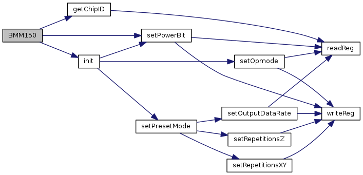
| BMM150 | ( | int | bus = BMM150_I2C_BUS, |
| int | addr = BMM150_DEFAULT_ADDR, |
||
| int | cs = -1 |
||
| ) |
BMM150 constructor.
This device can support both I2C and SPI. For SPI, set the addr to -1, and specify a positive integer representing the Chip Select (CS) pin for the cs argument. If you are using a hardware CS pin (like edison with arduino breakout), then you can connect the proper pin to the hardware CS pin on your MCU and supply -1 for cs. The default operating mode is I2C.
| bus | I2C or SPI bus to use. |
| addr | The address for this device. -1 for SPI. |
| cs | The gpio pin to use for the SPI Chip Select. -1 for I2C or for SPI with a hardware controlled pin. |
| theChipID | The chip ID to use for validation |
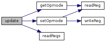
| void update | ( | void | ) |
Update the internal stored values from sensor data.

| uint8_t getChipID | ( | ) |
Return the chip ID.


| void getMagnetometer | ( | float * | x, |
| float * | y, | ||
| float * | z | ||
| ) |
Return magnetometer data in micro-Teslas (uT). update() must have been called prior to calling this method.
| x | Pointer to a floating point value that will have the current x component placed into it. |
| y | Pointer to a floating point value that will have the current y component placed into it. |
| z | Pointer to a floating point value that will have the current z component placed into it. |

| float * getMagnetometer | ( | ) |
Return magnetometer data in micro-Teslas (uT) in the form of a floating point array. The pointer returned by this function is statically allocated and will be rewritten on each call. update() must have been called prior to calling this method.
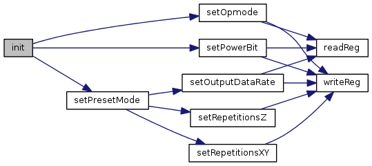
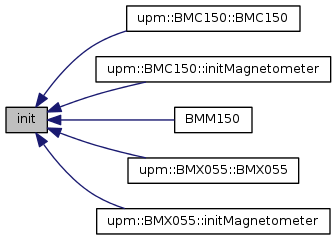
| void init | ( | USAGE_PRESETS_T | usage = USAGE_HIGH_ACCURACY | ) |
Initialize the device and start operation. This function is called from the constructor so will not typically need to be called by a user unless the device is reset. This method will call setPresetMode() with the passed parameter.
| usage | One of the USAGE_PRESETS_T values. The default is USAGE_HIGH_ACCURACY. |
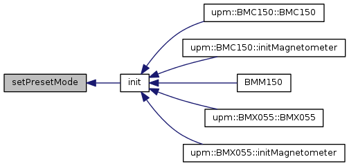
| void setPresetMode | ( | USAGE_PRESETS_T | usage | ) |
Set one of the Bosch recommended preset modes. These modes configure the sensor for varying use cases.
| usage | One of the USAGE_PRESETS_T values. The default is USAGE_HIGH_ACCURACY. |

| void reset | ( | ) |
Perform a device soft-reset. The device will be placed in SUSPEND mode afterward with all configured setting lost, so some re-initialization will be required to get data from the sensor. Calling init() will get everything running again.

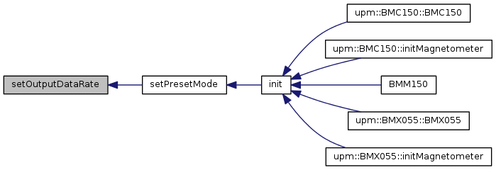
| void setOutputDataRate | ( | DATA_RATE_T | odr | ) |
Set the magnetometer Output Data Rate. See the datasheet for details.
| odr | One of the DATA_RATE_T values. |

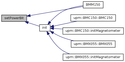
| void setPowerBit | ( | bool | power | ) |
Set or clear the Power bit. When the power bit is cleared, the device enters a deep suspend mode where only the REG_POWER_CTRL register can be accessed. This bit needs to be enabled for the device to operate. See the datasheet for details. The constructor enables this by default. After a deep suspend mode has been entered, all configured data is lost and the device must be reconfigured (as via init()).
| power | true to enable the bit, false otherwise. |

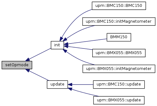
| void setOpmode | ( | OPERATION_MODE_T | opmode | ) |
Set the operating mode of the device. See the datasheet for details.
| power | One of the POWER_MODE_T values. |

| BMM150::OPERATION_MODE_T getOpmode | ( | ) |
Get the current operating mode of the device. See the datasheet for details. The power bit must be one for this method to succeed.


| uint8_t getInterruptEnable | ( | ) |
Return the Interrupt Enables register. This resgister allows you to enable various interrupt conditions. See the datasheet for details.

| void setInterruptEnable | ( | uint8_t | bits | ) |
Set the Interrupt Enables register. See the datasheet for details.
| bits | A bitmask of INT_EN_BITS_T bits. |

| uint8_t getInterruptConfig | ( | ) |
Return the Interrupt Config register. This register allows determining the electrical characteristics of the 2 interrupt pins (open-drain/push-pull and level/edge triggering) as well as other options. See the datasheet for details.

| void setInterruptConfig | ( | uint8_t | bits | ) |
Set the Interrupt Config register. This register allows determining the electrical characteristics of the 2 interrupt pins (open-drain/push-pull and level/edge triggering). See the datasheet for details.
| bits | A bitmask of INT_CONFIG_BITS_T bits. |

| uint8_t getInterruptStatus | ( | ) |
Return the interrupt status register. This register indicates which interrupts have been triggered. See the datasheet for details.

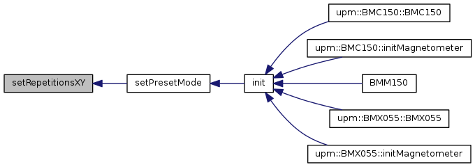
| void setRepetitionsXY | ( | uint8_t | reps | ) |
Set the repetion counter for the X and Y axes. This allows the device to average a number of measurements for a more stable output. See the datasheet for details.
| reps | A coefficient for specifying the number of repititions to perform. (1 + 2(reps)) |

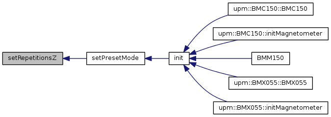
| void setRepetitionsZ | ( | uint8_t | reps | ) |
Set the repetion counter for the Z axis. This allows the device to average a number of measurements for a more stable output. See the datasheet for details.
| reps | A coefficient for specifying the number of repititions to perform. (1 + (reps)) |

| void installISR | ( | INTERRUPT_PINS_T | intr, |
| int | gpio, | ||
| mraa::Edge | level, | ||
| void(*)(void *) | isr, | ||
| void * | arg | ||
| ) |
install an interrupt handler.
| intr | one of the INTERRUPT_PINS_T values specifying which interrupt pin you are installing. |
| gpio | gpio pin to use as interrupt pin |
| level | the interrupt trigger level (one of mraa::Edge values). Make sure that you have configured the interrupt pin properly for whatever level you choose. |
| isr | the interrupt handler, accepting a void * argument |
| arg | the argument to pass the the interrupt handler |

| void uninstallISR | ( | INTERRUPT_PINS_T | intr | ) |
uninstall a previously installed interrupt handler
| intr | one of the INTERRUPT_PINS_T values specifying which interrupt pin you are removing. |

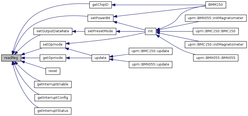
| uint8_t readReg | ( | uint8_t | reg | ) |
Read a register.
| reg | The register to read. |
| int readRegs | ( | uint8_t | reg, |
| uint8_t * | buffer, | ||
| int | len | ||
| ) |
Read contiguous registers into a buffer.
| buffer | The buffer to store the results. |
| len | The number of registers to read. |

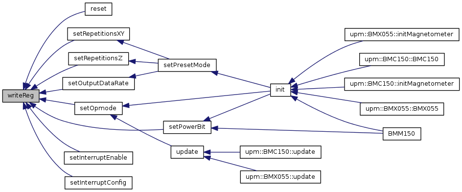
| void writeReg | ( | uint8_t | reg, |
| uint8_t | val | ||
| ) |
Write to a register
| reg | The register to write to. |
| val | The value to write. |
 1.8.6
1.8.6