|
upm
1.7.1
Sensor/Actuator repository for libmraa (v2.0.0)
|
|
upm
1.7.1
Sensor/Actuator repository for libmraa (v2.0.0)
|
API for the BMA250E 10 bit Triaxial Accelerometer. More...
The BMA250E is a triaxial, low-g acceleration sensor with digital output for consumer applications. It allows measurements of acceleration in three perpendicular axes. An evaluation circuitry (ASIC) converts the output of a micromechanical acceleration-sensing structure (MEMS) that works according to the differential capacitance principle.
Not all functionality of this chip has been implemented in this driver, however all the pieces are present to add any desired functionality. This driver supports both I2C (default) and SPI operation.
This driver attempts to support verious flavors of this chip, such as the version on the BMX050, BMI050 (chipid 0xfa) and the version on the bmc050 (chipid 0x03). Not all functionality is appropriate, or even present on all chips. Consult the relevant datasheets.
This device requires 3.3v operation.
Public Member Functions | |
| BMA250E (int bus=BMA250E_DEFAULT_I2C_BUS, int addr=BMA250E_DEFAULT_ADDR, int cs=-1) | |
| ~BMA250E () | |
| void | update () |
| uint8_t | getChipID () |
| void | getAccelerometer (float *x, float *y, float *z) |
| std::vector< float > | getAccelerometer () |
| float | getTemperature (bool fahrenheit=false) |
| void | init (BMA250E_POWER_MODE_T pwr=BMA250E_POWER_MODE_NORMAL, BMA250E_RANGE_T range=BMA250E_RANGE_2G, BMA250E_BW_T bw=BMA250E_BW_250) |
| void | reset () |
| void | setRange (BMA250E_RANGE_T range) |
| void | setBandwidth (BMA250E_BW_T bw) |
| void | setPowerMode (BMA250E_POWER_MODE_T power) |
| void | enableFIFO (bool useFIFO) |
| void | fifoSetWatermark (int wm) |
| void | fifoConfig (BMA250E_FIFO_MODE_T mode, BMA250E_FIFO_DATA_SEL_T axes) |
| void | setSelfTest (bool sign, bool amp, BMA250E_SELFTTEST_AXIS_T axis) |
| uint8_t | getInterruptEnable0 () |
| void | setInterruptEnable0 (uint8_t bits) |
| uint8_t | getInterruptEnable1 () |
| void | setInterruptEnable1 (uint8_t bits) |
| uint8_t | getInterruptEnable2 () |
| void | setInterruptEnable2 (uint8_t bits) |
| uint8_t | getInterruptMap0 () |
| void | setInterruptMap0 (uint8_t bits) |
| uint8_t | getInterruptMap1 () |
| void | setInterruptMap1 (uint8_t bits) |
| uint8_t | getInterruptMap2 () |
| void | setInterruptMap2 (uint8_t bits) |
| uint8_t | getInterruptSrc () |
| void | setInterruptSrc (uint8_t bits) |
| uint8_t | getInterruptOutputControl () |
| void | setInterruptOutputControl (uint8_t bits) |
| void | clearInterruptLatches () |
| BMA250E_RST_LATCH_T | getInterruptLatchBehavior () |
| void | setInterruptLatchBehavior (BMA250E_RST_LATCH_T latch) |
| uint8_t | getInterruptStatus0 () |
| uint8_t | getInterruptStatus1 () |
| uint8_t | getInterruptStatus2 () |
| uint8_t | getInterruptStatus3Bits () |
| BMA250E_ORIENT_T | getInterruptStatus3Orientation () |
| void | enableRegisterShadowing (bool shadow) |
| void | enableOutputFiltering (bool filter) |
| void | setLowPowerMode2 () |
| void | installISR (BMA250E_INTERRUPT_PINS_T intr, int gpio, mraa::Edge level, void(*isr)(void *), void *arg) |
| void | uninstallISR (BMA250E_INTERRUPT_PINS_T intr) |
| uint8_t | readReg (uint8_t reg) |
| int | readRegs (uint8_t reg, uint8_t *buffer, int len) |
| void | writeReg (uint8_t reg, uint8_t val) |
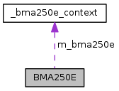
Protected Attributes | |
| bma250e_context | m_bma250e |
| BMA250E | ( | int | bus = BMA250E_DEFAULT_I2C_BUS, |
| int | addr = BMA250E_DEFAULT_ADDR, |
||
| int | cs = -1 |
||
| ) |
BMA250E constructor.
This device can support both I2C and SPI. For SPI, set the addr to -1, and specify a positive integer representing the Chip Select (CS) pin for the cs argument. If you are using a hardware CS pin (like edison with arduino breakout), then you can connect the proper pin to the hardware CS pin on your MCU and supply -1 for cs. The default operating mode is I2C.
| bus | I2C or SPI bus to use. |
| addr | The address for this device. -1 for SPI. |
| cs | The gpio pin to use for the SPI Chip Select. -1 for I2C or for SPI with a hardware controlled pin. |
| std::runtime_error | on initialization failure. |
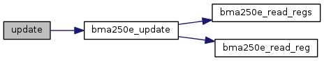
| void update | ( | void | ) |
Update the internal stored values from sensor data.
| std::runtime_error | on failure. |

| uint8_t getChipID | ( | ) |
Return the chip ID.

| void getAccelerometer | ( | float * | x, |
| float * | y, | ||
| float * | z | ||
| ) |
Return accelerometer data in gravities. update() must have been called prior to calling this method.
| x | Pointer to a floating point value that will have the current x component placed into it. |
| y | Pointer to a floating point value that will have the current y component placed into it. |
| z | Pointer to a floating point value that will have the current z component placed into it. |

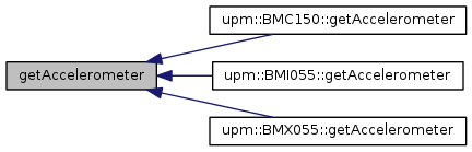
| std::vector< float > getAccelerometer | ( | ) |
Return accelerometer data in gravities in the form of a floating point vector. update() must have been called prior to calling this method.
| float getTemperature | ( | bool | fahrenheit = false | ) |
Return the current measured temperature. Note, this is not ambient temperature. update() must have been called prior to calling this method.
| fahrenheit | true to return data in Fahrenheit, false for Celicus. Celsius is the default. |

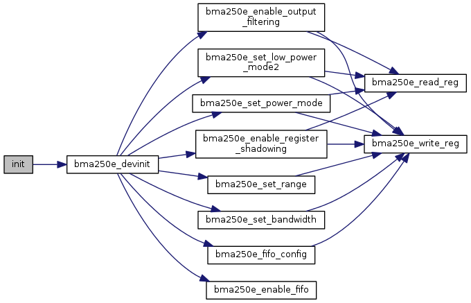
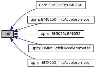
| void init | ( | BMA250E_POWER_MODE_T | pwr = BMA250E_POWER_MODE_NORMAL, |
| BMA250E_RANGE_T | range = BMA250E_RANGE_2G, |
||
| BMA250E_BW_T | bw = BMA250E_BW_250 |
||
| ) |
Initialize the device and start operation. This function is called from the constructor so will not typically need to be called by a user unless the device is reset.
| pwr | One of the BMA250E_POWER_MODE_T values. The default is BMA250E_POWER_MODE_NORMAL. |
| range | One of the BMA250E_RANGE_T values. The default is BMA250E_RANGE_2G. |
| bw | One of the filtering BMA250E_BW_T values. The default is BMA250E_BW_250. |
| std::runtime_error | on failure. |
| void reset | ( | ) |
| void setRange | ( | BMA250E_RANGE_T | range | ) |
Set the acceleration scaling range. This device supports 2, 4, 8, and 16g ranges.
| range | One of the BMA250E_RANGE_T values. |
| std::runtime_error | on failure. |

| void setBandwidth | ( | BMA250E_BW_T | bw | ) |
Set the output filtering bandwidth of the device.
| bw | One of the BMA250E_BW_T values. |
| std::runtime_error | on failure. |

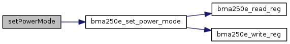
| void setPowerMode | ( | BMA250E_POWER_MODE_T | power | ) |
Set the power mode of the device. Care must be taken when setting a low power or suspend mode. By default init() calls setLowPowerMode2() to ensure that if any of these modes are entered we can still talk to the device. The default low power mode is LPM1, which requires slowing down register writes, which we cannot support. setLowPowerMode2() enables LPM2 which keeps the digital interface operational in low power or suspend modes. See the datasheet for details.
So if you reset your device and don't call init() or setLowPowerMode2(), you could lose control of the device by calling this function with anything other than POWER_MODE_NORMAL. You've been warned :)
| power | One of the BMA250E_POWER_MODE_T values. |
| std::runtime_error | on failure. |
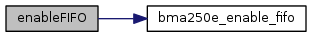
| void enableFIFO | ( | bool | useFIFO | ) |
Enable update() to read from the FIFO rather than the acceleration axis registers directly. init() enables this mode by default if the chip variant supports a FIFO. An advantage to this mode that all axis data is sampled from the same timeslice. When reading directly from the acceleration output registers, it's possible for one axis to be updated while another is being read, causing a temporal anomaly that even Captain Picard can't resolve. If there is no FIFO present, this call is ignored.
Using the FIFO removes this problem.
| useFIFO | True to enable update() to read from the FIFO. When false, update will read from the acceleration output registers directly. |
| void fifoSetWatermark | ( | int | wm | ) |
Set the FIFO watermark. When the watermark is reached an interrupt (if enabled) will be generated. If there is no FIFO present, this call is ignored.
| wm | The FIFO watermark to use. The maximum value is 63. |
| std::runtime_error | on failure. |

| void fifoConfig | ( | BMA250E_FIFO_MODE_T | mode, |
| BMA250E_FIFO_DATA_SEL_T | axes | ||
| ) |
Set the FIFO configuration. init() uses the FIFO_MODE_BYPASS mode with axes set to FIFO_DATA_SEL_XYZ by default. If there is no FIFO present, this call is ignored.
| mode | One of the BMA250E_FIFO_MODE_T values. |
| axes | One of the BMA250E_FIFO_DATA_SEL_T values. |
| std::runtime_error | on failure. |

| void setSelfTest | ( | bool | sign, |
| bool | amp, | ||
| BMA250E_SELFTTEST_AXIS_T | axis | ||
| ) |
Enable, disable, and configure the built in self test on a per axis basis. See the datasheet for details.
| sign | True for a positive deflection, false for negative |
| amp | True for a high deflection, false for a low deflection |
| axis | One of the BMA250E_SELFTTEST_AXIS_T values. Note, only one axis at a time can be tested. Accelerometer output for other axes should be ignored. |
| std::runtime_error | on failure. |

| uint8_t getInterruptEnable0 | ( | ) |
Return the Interrupt Enables 0 register. These registers allow you to enable various interrupt conditions. See the datasheet for details.

| void setInterruptEnable0 | ( | uint8_t | bits | ) |
Set the Interrupt Enables 0 register. See the datasheet for details.
| bits | A bitmask of BMA250E_INT_EN_0_BITS_T bits. |
| std::runtime_error | on failure. |

| uint8_t getInterruptEnable1 | ( | ) |
Return the Interrupt Enables 1 register. See the datasheet for details.

| void setInterruptEnable1 | ( | uint8_t | bits | ) |
Set the Interrupt Enables 1 register. See the datasheet for details.
| bits | A bitmask of BMA250E_INT_EN_1_BITS_T bits. |
| std::runtime_error | on failure. |

| uint8_t getInterruptEnable2 | ( | ) |
Return the Interrupt Enables 2 register. See the datasheet for details.

| void setInterruptEnable2 | ( | uint8_t | bits | ) |
Set the Interrupt Enables 2 register. See the datasheet for details.
| bits | A bitmask of BMA250E_INT_EN_2_BITS_T bits. |
| std::runtime_error | on failure. |

| uint8_t getInterruptMap0 | ( | ) |
Return the Interrupt Map 0 register. These registers allow you to map specific interrupts to the interrupt 1 or interrupt 2 pin. See the datasheet for details.

| void setInterruptMap0 | ( | uint8_t | bits | ) |
Set the Interrupt Map 0 register. These registers allow you to map specific interrupts to the interrupt 1 or interrupt 2 pin. See the datasheet for details.
| bits | A bitmask of BMA250E_INT_MAP_0_BITS_T bits. |
| std::runtime_error | on failure. |

| uint8_t getInterruptMap1 | ( | ) |
Return the Interrupt Map 1 register. See the datasheet for details.

| void setInterruptMap1 | ( | uint8_t | bits | ) |
Set the Interrupt Map 1 register. See the datasheet for details.
| bits | A bitmask of BMA250E_INT_MAP_1_BITS_T bits. |
| std::runtime_error | on failure. |

| uint8_t getInterruptMap2 | ( | ) |
Return the Interrupt Map 2 register. See the datasheet for details.

| void setInterruptMap2 | ( | uint8_t | bits | ) |
Set the Interrupt Map 2 register. See the datasheet for details.
| bits | A bitmask of BMA250E_INT_MAP_2_BITS_T bits. |
| std::runtime_error | on failure. |

| uint8_t getInterruptSrc | ( | ) |
Return the Interrupt source register. This register allows determining where data comes from (filtered/unfiltered) for those interrupt sources where this is selectable. See the datasheet for details.

| void setInterruptSrc | ( | uint8_t | bits | ) |
Set the Interrupt source register. This register allows determining where data comes from (filtered/unfiltered) for those interrupt sources where this is selectable. See the datasheet for details.
| bits | A bitmask of BMA250E_INT_SRC_BITS_T bits. |
| std::runtime_error | on failure. |

| uint8_t getInterruptOutputControl | ( | ) |
Return the Interrupt output control register. This register allows determining the electrical characteristics of the 2 interrupt pins (open-drain/push-pull and level/edge triggering). See the datasheet for details.

| void setInterruptOutputControl | ( | uint8_t | bits | ) |
Set the Interrupt output control register. This register allows determining the electrical characteristics of the 2 interrupt pins (open-drain/push-pull and level/edge triggering). See the datasheet for details.
| bits | A bitmask of BMA250E_INT_OUT_CTRL_BITS_T bits. |
| std::runtime_error | on failure. |

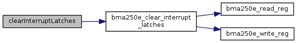
| void clearInterruptLatches | ( | ) |
Clear all latched interrupts. See the datasheet for details.
| std::runtime_error | on failure. |
| BMA250E_RST_LATCH_T getInterruptLatchBehavior | ( | ) |
Return the current interrupt latching behavior. See the datasheet for details.

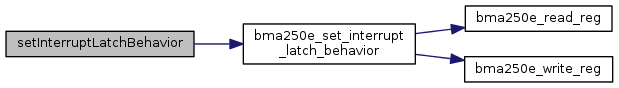
| void setInterruptLatchBehavior | ( | BMA250E_RST_LATCH_T | latch | ) |
Set the current interrupt latching behavior. See the datasheet for details.
| latch | One of the BMA250E_RST_LATCH_T values. |
| std::runtime_error | on failure. |
| uint8_t getInterruptStatus0 | ( | ) |
Return the interrupt status 0 register. These registers indicate which interrupts have been triggered. See the datasheet for details.

| uint8_t getInterruptStatus1 | ( | ) |
Return the interrupt status 1 register. See the datasheet for details.

| uint8_t getInterruptStatus2 | ( | ) |
Return the interrupt status 2 register. See the datasheet for details.

| uint8_t getInterruptStatus3Bits | ( | ) |
Return the interrupt status 3 register bitfields. See the datasheet for details. The Orientation value is not returned by this function, see getInterruptStatus3Orientation() for that information.

| BMA250E_ORIENT_T getInterruptStatus3Orientation | ( | ) |
Return the interrupt status 3 register Orientation value. See the datasheet for details.

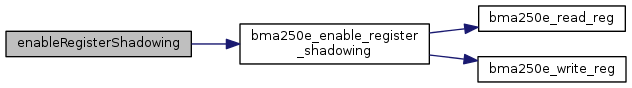
| void enableRegisterShadowing | ( | bool | shadow | ) |
Enable shadowing of the accelerometer output registers. When enabled, a read of an axis LSB register automatically locks the MSB register of that axis until it has been read. This is usually a good thing to have enabled. init() enables this by default. If disabled, then it becomes possible for part of an axis value to change while another part is being read, causing inconsistent data.
| shadow | True to enable axis register shadowing, false otherwise. |
| std::runtime_error | on failure. |
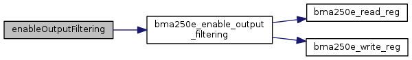
| void enableOutputFiltering | ( | bool | filter | ) |
Enable filtering of the accelerometer axis data. init() enables this by default. If disabled, then accelerometer data that is read will be raw and unfiltered (rated R). See the datasheet for details.
| filter | True to enable filtering, false to disable. |
| std::runtime_error | on failure. |
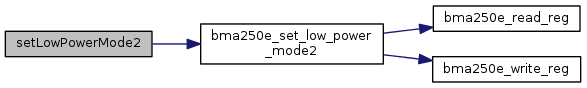
| void setLowPowerMode2 | ( | ) |
Make sure low power mode config (LPM2) is set in case we later go into the low power or suspend power modes. LPM1 mode (the default) requires drastically slowed register writes which we cannot handle.
| std::runtime_error | on failure. |
| void installISR | ( | BMA250E_INTERRUPT_PINS_T | intr, |
| int | gpio, | ||
| mraa::Edge | level, | ||
| void(*)(void *) | isr, | ||
| void * | arg | ||
| ) |
install an interrupt handler.
| intr | One of the BMA250E_INTERRUPT_PINS_T values specifying which interrupt pin you are installing. |
| gpio | GPIO pin to use as interrupt pin. |
| level | The interrupt trigger level (one of mraa::Edge values). Make sure that you have configured the interrupt pin properly for whatever level you choose. |
| isr | The interrupt handler, accepting a void * argument. |
| arg | The argument to pass the the interrupt handler. |
| std::runtime_error | on failure. |

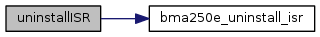
| void uninstallISR | ( | BMA250E_INTERRUPT_PINS_T | intr | ) |
uninstall a previously installed interrupt handler
| intr | One of the BMA250E_INTERRUPT_PINS_T values specifying which interrupt pin you are removing. |
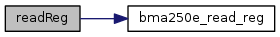
| uint8_t readReg | ( | uint8_t | reg | ) |
Read a register.
| reg | The register to read. |
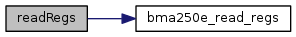
| int readRegs | ( | uint8_t | reg, |
| uint8_t * | buffer, | ||
| int | len | ||
| ) |
Read contiguous registers into a buffer.
| buffer | The buffer to store the results. |
| len | The number of registers to read. |
| std::runtime_error | on failure. |
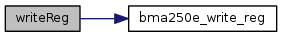
| void writeReg | ( | uint8_t | reg, |
| uint8_t | val | ||
| ) |
Write to a register.
| reg | The register to write to. |
| val | The value to write. |
| std::runtime_error | on failure. |
 1.8.11


