|
upm
1.7.1
Sensor/Actuator repository for libmraa (v2.0.0)
|
|
upm
1.7.1
Sensor/Actuator repository for libmraa (v2.0.0)
|
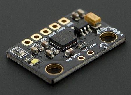
API for the MPU60X0 3-axis Gyroscope and 3-axis Accelerometer. More...
The MPU60X0 devices provide the world's first integrated 6-axis motion processor solution that eliminates the package-level gyroscope and accelerometer cross-axis misalignment associated with discrete solutions. The devices combine a 3-axis gyroscope and a 3-axis accelerometer on the same silicon die.
While not all of the functionality of this device is supported initially, methods and register definitions are provided that should allow an end user to implement whatever features are required.
Public Types | |
| enum | MPU60X0_REG_T { REG_SELF_TEST_X = 0x0d, REG_SELF_TEST_Y = 0x0e, REG_SELF_TEST_Z = 0x0f, REG_SELF_TEST_A = 0x10, REG_SMPLRT_DIV = 0x19, REG_CONFIG = 0x1a, REG_GYRO_CONFIG = 0x1b, REG_ACCEL_CONFIG = 0x1c, REG_FF_THR = 0x1d, REG_FF_DUR = 0x1e, REG_MOT_THR = 0x1f, REG_MOT_DUR = 0x20, REG_ZRMOT_THR = 0x21, REG_ZRMOT_DUR = 0x22, REG_FIFO_EN = 0x23, REG_I2C_MST_CTRL = 0x24, REG_I2C_SLV0_ADDR = 0x25, REG_I2C_SLV0_REG = 0x26, REG_I2C_SLV0_CTRL = 0x27, REG_I2C_SLV1_ADDR = 0x28, REG_I2C_SLV1_REG = 0x29, REG_I2C_SLV1_CTRL = 0x2a, REG_I2C_SLV2_ADDR = 0x2b, REG_I2C_SLV2_REG = 0x2c, REG_I2C_SLV2_CTRL = 0x2d, REG_I2C_SLV3_ADDR = 0x2e, REG_I2C_SLV3_REG = 0x2f, REG_I2C_SLV3_CTRL = 0x30, REG_I2C_SLV4_ADDR = 0x31, REG_I2C_SLV4_REG = 0x32, REG_I2C_SLV4_DO = 0x33, REG_I2C_SLV4_CTRL = 0x34, REG_I2C_SLV4_DI = 0x35, REG_I2C_MST_STATUS = 0x36, REG_INT_PIN_CFG = 0x37, REG_INT_ENABLE = 0x38, REG_INT_STATUS = 0x3a, REG_ACCEL_XOUT_H = 0x3b, REG_ACCEL_XOUT_L = 0x3c, REG_ACCEL_YOUT_H = 0x3d, REG_ACCEL_YOUT_L = 0x3e, REG_ACCEL_ZOUT_H = 0x3f, REG_ACCEL_ZOUT_L = 0x40, REG_TEMP_OUT_H = 0x41, REG_TEMP_OUT_L = 0x42, REG_GYRO_XOUT_H = 0x43, REG_GYRO_XOUT_L = 0x44, REG_GYRO_YOUT_H = 0x45, REG_GYRO_YOUT_L = 0x46, REG_GYRO_ZOUT_H = 0x47, REG_GYRO_ZOUT_L = 0x48, REG_EXT_SENS_DATA_00 = 0x49, REG_EXT_SENS_DATA_01 = 0x4a, REG_EXT_SENS_DATA_02 = 0x4b, REG_EXT_SENS_DATA_03 = 0x4c, REG_EXT_SENS_DATA_04 = 0x4d, REG_EXT_SENS_DATA_05 = 0x4e, REG_EXT_SENS_DATA_06 = 0x4f, REG_EXT_SENS_DATA_07 = 0x50, REG_EXT_SENS_DATA_08 = 0x51, REG_EXT_SENS_DATA_09 = 0x52, REG_EXT_SENS_DATA_10 = 0x53, REG_EXT_SENS_DATA_11 = 0x54, REG_EXT_SENS_DATA_12 = 0x55, REG_EXT_SENS_DATA_13 = 0x56, REG_EXT_SENS_DATA_14 = 0x57, REG_EXT_SENS_DATA_15 = 0x58, REG_EXT_SENS_DATA_16 = 0x59, REG_EXT_SENS_DATA_17 = 0x5a, REG_EXT_SENS_DATA_18 = 0x5b, REG_EXT_SENS_DATA_19 = 0x5c, REG_EXT_SENS_DATA_20 = 0x5d, REG_EXT_SENS_DATA_21 = 0x5e, REG_EXT_SENS_DATA_22 = 0x5f, REG_EXT_SENS_DATA_23 = 0x60, REG_MOT_DETECT_STATUS = 0x61, REG_I2C_SLV0_DO = 0x63, REG_I2C_SLV1_DO = 0x64, REG_I2C_SLV2_DO = 0x65, REG_I2C_SLV3_DO = 0x66, REG_I2C_MST_DELAY_CTRL = 0x67, REG_SIGNAL_PATH_RESET = 0x68, REG_MOT_DETECT_CTRL = 0x69, REG_USER_CTRL = 0x6a, REG_PWR_MGMT_1 = 0x6b, REG_PWR_MGMT_2 = 0x6c, REG_FIFO_COUNTH = 0x72, REG_FIFO_COUNTL = 0x73, REG_FIFO_R_W = 0x74, REG_WHO_AM_I = 0x75 } |
| enum | CONFIG_BITS_T { CONFIG_DLPF_CFG0 = 0x01, CONFIG_DLPF_CFG1 = 0x02, CONFIG_DLPF_CFG2 = 0x04, _CONFIG_DLPF_SHIFT = 0, _CONFIG_DLPF_MASK = 7, CONFIG_EXT_SYNC_SET0 = 0x08, CONFIG_EXT_SYNC_SET1 = 0x10, CONFIG_EXT_SYNC_SET2 = 0x20, _CONFIG_EXT_SYNC_SET_SHIFT = 3, _CONFIG_EXT_SYNC_SET_MASK = 7 } |
| enum | DLPF_CFG_T { DLPF_260_256 = 0, DLPF_184_188 = 1, DLPF_94_98 = 2, DLPF_44_42 = 3, DLPF_21_20 = 4, DLPF_10_10 = 5, DLPF_5_5 = 6, DLPF_RESERVED = 7 } |
| enum | EXT_SYNC_SET_T { EXT_SYNC_DISABLED = 0, EXT_SYNC_TEMP_OUT = 1, EXT_SYNC_GYRO_XOUT = 2, EXT_SYNC_GYRO_YOUT = 3, EXT_SYNC_GYRO_ZOUT = 4, EXT_SYNC_ACCEL_XOUT = 5, EXT_SYNC_ACCEL_YOUT = 6, EXT_SYNC_ACCEL_ZOUT = 7 } |
| enum | GRYO_CONFIG_BITS_T { FS_SEL0 = 0x08, FS_SEL1 = 0x10, _FS_SEL_SHIFT = 3, _FS_SEL_MASK = 3, ZG_ST = 0x20, YG_ST = 0x40, XG_ST = 0x80 } |
| enum | FS_SEL_T { FS_250 = 0, FS_500 = 1, FS_1000 = 2, FS_2000 = 3 } |
| enum | ACCEL_CONFIG_BITS_T { AFS_SEL0 = 0x08, AFS_SEL1 = 0x10, _AFS_SEL_SHIFT = 3, _AFS_SEL_MASK = 3, ZA_ST = 0x20, YA_ST = 0x40, XA_ST = 0x80 } |
| enum | AFS_SEL_T { AFS_2 = 0, AFS_4 = 1, AFS_8 = 2, AFS_16 = 3 } |
| enum | FIFO_EN_BITS_T { SLV0_FIFO_EN = 0x01, SLV1_FIFO_EN = 0x02, SLV2_FIFO_EN = 0x04, ACCEL_FIFO_EN = 0x08, ZG_FIFO_EN = 0x10, YG_FIFO_EN = 0x20, XG_FIFO_EN = 0x40, TEMP_FIFO_EN = 0x80 } |
| enum | I2C_MST_CTRL_BITS_T { I2C_MST_CLK0 = 0x01, I2C_MST_CLK1 = 0x02, I2C_MST_CLK2 = 0x04, I2C_MST_CLK3 = 0x08, _I2C_MST_CLK_SHIFT = 0, _I2C_MST_CLK_MASK = 15, I2C_MST_P_NSR = 0x10, SLV_3_FIFO_EN = 0x20, WAIT_FOR_ES = 0x40, MULT_MST_EN = 0x80 } |
| enum | I2C_MST_CLK_T { MST_CLK_348 = 0, MST_CLK_333 = 1, MST_CLK_320 = 2, MST_CLK_308 = 3, MST_CLK_296 = 4, MST_CLK_286 = 5, MST_CLK_276 = 6, MST_CLK_267 = 7, MST_CLK_258 = 8, MST_CLK_500 = 9, MST_CLK_471 = 10, MST_CLK_444 = 11, MST_CLK_421 = 12, MST_CLK_400 = 13, MST_CLK_381 = 14, MST_CLK_364 = 15 } |
| enum | I2C_SLV_ADDR_BITS_T { I2C_SLV_ADDR0 = 0x01, I2C_SLV_ADDR1 = 0x02, I2C_SLV_ADDR2 = 0x04, I2C_SLV_ADDR3 = 0x08, I2C_SLV_ADDR4 = 0x10, I2C_SLV_ADDR5 = 0x20, I2C_SLV_ADDR6 = 0x40, _I2C_SLV_ADDR_SHIFT = 0, _I2C_SLV_ADDR_MASK = 127, I2C_SLV_RW = 0x80 } |
| enum | I2C_SLV_CTRL_BITS_T { I2C_SLV_LEN0 = 0x01, I2C_SLV_LEN1 = 0x02, I2C_SLV_LEN2 = 0x04, I2C_SLV_LEN3 = 0x08, _I2C_SLV_LEN_SHIFT = 0, _I2C_SLV_LEN_MASK = 15, I2C_SLV_GRP = 0x10, I2C_SLV_REG_DIS = 0x20, I2C_SLV_BYTE_SW = 0x40, I2C_SLV_EN = 0x80 } |
| enum | I2C_SLV4_CTRL_BITS_T { I2C_MST_DLY0 = 0x01, I2C_MST_DLY1 = 0x02, I2C_MST_DLY2 = 0x04, I2C_MST_DLY3 = 0x08, I2C_MST_DLY4 = 0x10, _I2C_MST_DLY_SHIFT = 0, _I2C_MST_DLY_MASK = 31, I2C_SLV4_REG_DIS = 0x20, I2C_SLV4_INT_EN = 0x40, I2C_SLV4_EN = 0x80 } |
| enum | I2C_MST_STATUS_BITS_T { I2C_SLV0_NACK = 0x01, I2C_SLV1_NACK = 0x02, I2C_SLV2_NACK = 0x04, I2C_SLV3_NACK = 0x08, I2C_SLV4_NACK = 0x10, I2C_LOST_ARB = 0x20, I2C_SLV4_DONE = 0x40, PASS_THROUGH = 0x80 } |
| enum | INT_PIN_CFG_BITS_T { CLKOUT_EN = 0x01, I2C_BYPASS_ENABLE = 0x02, FSYNC_INT_EN = 0x04, FSYNC_INT_LEVEL = 0x08, INT_RD_CLEAR = 0x10, LATCH_INT_EN = 0x20, INT_OPEN = 0x40, INT_LEVEL = 0x80 } |
| enum | INT_ENABLE_BITS_T { DATA_RDY_EN = 0x01, I2C_MST_INT_EN = 0x08, FIFO_OFLOW_EN = 0x10, ZMOT_EN = 0x20, MOT_EN = 0x40, FF_EN = 0x80 } |
| enum | INT_STATUS_BITS_T { DATA_RDY_INT = 0x01, I2C_MST_INT = 0x08, FIFO_OFLOW_INT = 0x10, ZMOT_INT = 0x20, MOT_INT = 0x40, FF_INT = 0x80 } |
| enum | MOT_DETECT_STATUS_BITS_T { MOT_ZRMOT = 0x01, MOT_ZPOS = 0x04, MOT_ZNEG = 0x08, MOT_YPOS = 0x10, MOT_YNEG = 0x20, MOT_XPOS = 0x40, MOT_XNEG = 0x80 } |
| enum | MST_DELAY_CTRL_BITS_T { I2C_SLV0_DLY_EN = 0x01, I2C_SLV1_DLY_EN = 0x02, I2C_SLV2_DLY_EN = 0x04, I2C_SLV3_DLY_EN = 0x08, I2C_SLV4_DLY_EN = 0x10, DELAY_ES_SHADOW = 0x80 } |
| enum | SIGNAL_PATH_RESET_BITS_T { TEMP_RESET = 0x01, ACCEL_RESET = 0x02, GYRO_RESET = 0x04 } |
| enum | MOT_DETECT_CTRL_BITS_T { MOT_COUNT0 = 0x01, MOT_COUNT1 = 0x02, _MOT_COUNT_SHIFT = 0, _MOT_COUNT_MASK = 3, FF_COUNT0 = 0x04, FF_COUNT1 = 0x08, _FF_COUNT_SHIFT = 2, _FF_COUNT_MASK = 3, ACCEL_ON_DELAY0 = 0x10, ACCEL_ON_DELAY1 = 0x20, _ACCEL_ON_DELAY_SHIFT = 4, _ACCEL_ON_DELAY_MASK = 3 } |
| enum | MOT_FF_COUNT_T { COUNT_0 = 0, COUNT_1 = 1, COUNT_2 = 2, COUNT_4 = 3 } |
| enum | ACCEL_ON_DELAY_T { ON_DELAY_0 = 0, ON_DELAY_1 = 1, ON_DELAY_2 = 2, ON_DELAY_3 = 3 } |
| enum | USER_CTRL_BITS_T { SIG_COND_RESET = 0x01, I2C_MST_RESET = 0x02, FIFO_RESET = 0x04, I2C_IF_DIS = 0x10, I2C_MST_EN = 0x20, FIFO_EN = 0x40 } |
| enum | PWR_MGMT_1_BITS_T { CLKSEL0 = 0x01, CLKSEL1 = 0x02, CLKSEL2 = 0x04, _CLKSEL_SHIFT = 0, _CLKSEL_MASK = 7, TEMP_DIS = 0x08, PWR_CYCLE = 0x20, PWR_SLEEP = 0x40, DEVICE_RESET = 0x80 } |
| enum | CLKSEL_T { INT_8MHZ = 0, PLL_XG = 1, PLL_YG = 2, PLL_ZG = 3, PLL_EXT_32KHZ = 4, PLL_EXT_19MHZ = 5, CLK_STOP = 7 } |
| enum | PWR_MGMT_2_BITS_T { STBY_ZG = 0x01, STBY_YG = 0x02, STBY_XG = 0x04, STBY_ZA = 0x08, STBY_YA = 0x10, STBY_XA = 0x20, LP_WAKE_CTRL0 = 0x40, LP_WAKE_CTRL1 = 0x80, _LP_WAKE_CTRL_SHIFT = 6, _LP_WAKE_CTRL_MASK = 3 } |
| enum | LP_WAKE_CRTL_T { LP_WAKE_1_25 = 0, LP_WAKE_5 = 1, LP_WAKE_20 = 2, LP_WAKE_40 = 3 } |
Public Member Functions | |
| MPU60X0 (int bus=MPU60X0_I2C_BUS, uint8_t address=MPU60X0_DEFAULT_I2C_ADDR) | |
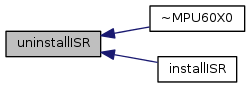
| virtual | ~MPU60X0 () |
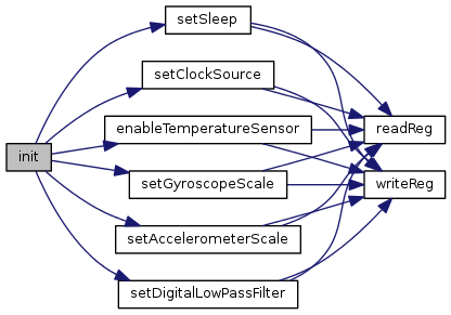
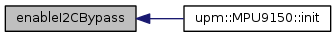
| bool | init () |
| void | update () |
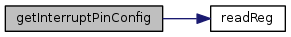
| uint8_t | readReg (uint8_t reg) |
| void | readRegs (uint8_t reg, uint8_t *buffer, int len) |
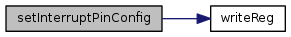
| bool | writeReg (uint8_t reg, uint8_t val) |
| bool | setSleep (bool enable) |
| bool | setClockSource (CLKSEL_T clk) |
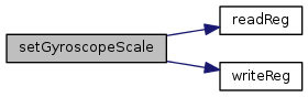
| bool | setGyroscopeScale (FS_SEL_T scale) |
| bool | setAccelerometerScale (AFS_SEL_T scale) |
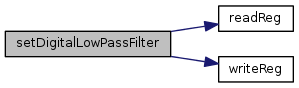
| bool | setDigitalLowPassFilter (DLPF_CFG_T dlp) |
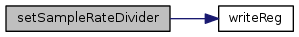
| bool | setSampleRateDivider (uint8_t div) |
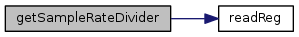
| uint8_t | getSampleRateDivider () |
| void | getAccelerometer (float *x, float *y, float *z) |
| void | getGyroscope (float *x, float *y, float *z) |
| virtual float | getTemperature () |
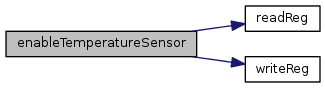
| bool | enableTemperatureSensor (bool enable) |
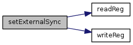
| bool | setExternalSync (EXT_SYNC_SET_T val) |
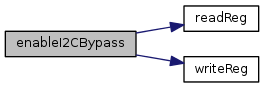
| bool | enableI2CBypass (bool enable) |
| bool | setMotionDetectionThreshold (uint8_t thr) |
| uint8_t | getInterruptStatus () |
| bool | setInterruptEnables (uint8_t enables) |
| uint8_t | getInterruptEnables () |
| bool | setInterruptPinConfig (uint8_t cfg) |
| uint8_t | getInterruptPinConfig () |
| void | installISR (int gpio, mraa::Edge level, void(*isr)(void *), void *arg) |
| void | uninstallISR () |
| mraa::Gpio * | get_gpioIRQ () |
Protected Attributes | |
| float | m_accelX |
| float | m_accelY |
| float | m_accelZ |
| float | m_gyroX |
| float | m_gyroY |
| float | m_gyroZ |
| float | m_temp |
| float | m_accelScale |
| float | m_gyroScale |
| enum MPU60X0_REG_T |
MPU60X0 registers
| enum CONFIG_BITS_T |
CONFIG bits
| enum DLPF_CFG_T |
CONFIG DLPF_CFG values
| enum EXT_SYNC_SET_T |
CONFIG EXT_SYNC_SET values
| enum GRYO_CONFIG_BITS_T |
GYRO_CONFIG bits
| enum FS_SEL_T |
GYRO FS_SEL values
| enum ACCEL_CONFIG_BITS_T |
ACCEL_CONFIG bits
| enum AFS_SEL_T |
ACCEL AFS_SEL (full scaling) values
| enum FIFO_EN_BITS_T |
REG_FIFO_EN bits
| enum I2C_MST_CTRL_BITS_T |
REG_I2C_MST_CTRL bits
| enum I2C_MST_CLK_T |
I2C_MST_CLK values
| enum I2C_SLV_ADDR_BITS_T |
REG_I2C SLV0-SLV4 _ADDR bits
| enum I2C_SLV_CTRL_BITS_T |
REG_I2C SLV0-SLV3 _CTRL bits
| enum I2C_SLV4_CTRL_BITS_T |
REG_I2C_SLV4_CTRL bits, these are different from the SLV0-SLV3 CRTL bits.
MST_DLY is not enumerated in the register map. It configures the reduced access rate of i2c slaves relative to the sample rate. When a slave's access rate is decreased relative to the Sample Rate, the slave is accessed every 1 / (1 + I2C_MST_DLY) samples
REG_I2C_MST_STATUS bits
| enum INT_PIN_CFG_BITS_T |
REG_INT_PIN_CFG bits
| enum INT_ENABLE_BITS_T |
REG_INT_ENABLE bits
| enum INT_STATUS_BITS_T |
REG_INT_STATUS bits
REG_MOT_DETECT_STATUS bits (mpu9150 only)
REG_MST_DELAY_CTRL bits
REG_SIGNAL_PATH_RESET bits
REG_MOT_DETECT_CTRL bits
| enum MOT_FF_COUNT_T |
MOT_COUNT or FF_COUNT values (mpu9150 only)
| enum ACCEL_ON_DELAY_T |
ACCEL_ON_DELAY values
| enum USER_CTRL_BITS_T |
REG_USER_CTRL bits
| enum PWR_MGMT_1_BITS_T |
REG_PWR_MGMT_1 bits
| enum CLKSEL_T |
CLKSEL values
| enum PWR_MGMT_2_BITS_T |
REG_PWR_MGMT_2 bits
| enum LP_WAKE_CRTL_T |
LP_WAKE_CTRL values
| MPU60X0 | ( | int | bus = MPU60X0_I2C_BUS, |
| uint8_t | address = MPU60X0_DEFAULT_I2C_ADDR |
||
| ) |
mpu60x0 constructor
| bus | i2c bus to use |
| address | the address for this device |
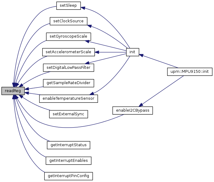
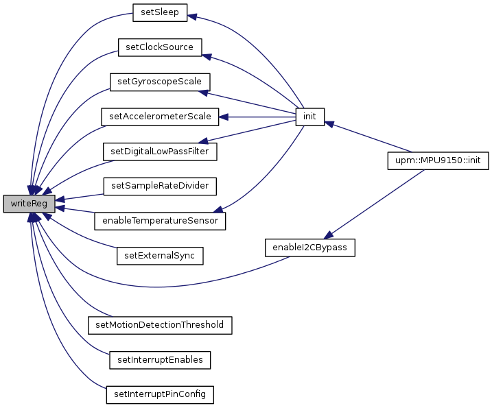
| bool init | ( | ) |
set up initial values and start operation
| void update | ( | void | ) |
take a measurement and store the current sensor values internally. Note, these user facing registers are only updated from the internal device sensor values when the i2c serial traffic is 'idle'. So, if you are reading the values too fast, the bus may never be idle, and you will just end up reading the same values over and over.
Unfortunately, it is is not clear how long 'idle' actually means, so if you see this behavior, reduce the rate at which you are calling update().


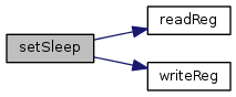
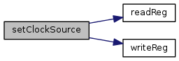
| uint8_t readReg | ( | uint8_t | reg | ) |
read a register
| reg | the register to read |
| void readRegs | ( | uint8_t | reg, |
| uint8_t * | buffer, | ||
| int | len | ||
| ) |
read contiguous refister into a buffer
| reg | the register to start reading at |
| buffer | the buffer to store the results |
| len | the number of registers to read |

| bool writeReg | ( | uint8_t | reg, |
| uint8_t | val | ||
| ) |
write to a register
| reg | the register to write to |
| val | the value to write |
| bool setSleep | ( | bool | enable | ) |
enable or disable device sleep
| enable | true to put device to sleep, false to wake up |

| bool setClockSource | ( | CLKSEL_T | clk | ) |
specify the clock source for the device to use
| clk | one of the CLKSEL_T values |

| bool setGyroscopeScale | ( | FS_SEL_T | scale | ) |
set the scaling mode of the gyroscope
| scale | one of the FS_SEL_T values |

| bool setAccelerometerScale | ( | AFS_SEL_T | scale | ) |
set the scaling mode of the accelerometer
| scale | one of the AFS_SEL_T values |


| bool setDigitalLowPassFilter | ( | DLPF_CFG_T | dlp | ) |
set the Low Pass Digital filter. This enables filtering (if non-0) of the accelerometer and gyro outputs.
| dlp | one of the DLPF_CFG_T values |

| bool setSampleRateDivider | ( | uint8_t | div | ) |
set the sample rate divider. This register specifies the divider from the gyro output rate used to generate the Sample Rate. The sensor registor output, FIFO output, DMP sampling and motion detection are all based on the Sample Rate.
The Sample Rate is generated by dividing the gyro output rate by this register:
Sample Rate = Gyro output rate / (1 + sample rate divider).
The Gyro output rate is 8Khz when the Digital Low Pass Filter (DLPF) is 0 or 7 (DLPF_260_256 or DLPF_RESERVED), and 1Khz otherwise.
| div | one of the DLPF_CFG_T values |
| uint8_t getSampleRateDivider | ( | ) |
get the current Sample Rate divider
| void getAccelerometer | ( | float * | x, |
| float * | y, | ||
| float * | z | ||
| ) |
get the accelerometer values
| x | the returned x value, if arg is non-NULL |
| y | the returned y value, if arg is non-NULL |
| z | the returned z value, if arg is non-NULL |
| void getGyroscope | ( | float * | x, |
| float * | y, | ||
| float * | z | ||
| ) |
get the gyroscope values
| x | the returned x value, if arg is non-NULL |
| y | the returned y value, if arg is non-NULL |
| z | the returned z value, if arg is non-NULL |
|
virtual |
| bool enableTemperatureSensor | ( | bool | enable | ) |
enable onboard temperature measurement sensor
| enable | true to enable temperature sensor, false to disable |

| bool setExternalSync | ( | EXT_SYNC_SET_T | val | ) |
configure external sync. An external signal connected to the FSYNC pin can be sampled by configuring EXT_SYNC_SET. Signal changes to the FSYNC pin are latched so that short strobes may be captured. The latched FSYNC signal will be sampled at the Sampling Rate, as defined in register 25. After sampling, the latch will reset to the current FSYNC signal state.
The sampled value will be reported in place of the least significant bit in a sensor data register determined by the value of EXT_SYNC_SET
| val | one of the EXT_SYNC_SET_T values |
| bool enableI2CBypass | ( | bool | enable | ) |
enable I2C Bypass. Enabling this feature allows devices on the MPU60X0 auxiliary I2C bus to be visible on the MCU's I2C bus.
| enable | true to I2C bypass |
| bool setMotionDetectionThreshold | ( | uint8_t | thr | ) |
set the motion detection threshold for interrupt generation. Motion is detected when the absolute value of any of the accelerometer measurements exceeds this Motion detection threshold.
| thr | threshold |
| uint8_t getInterruptStatus | ( | ) |
return the interrupt status register.
| bool setInterruptEnables | ( | uint8_t | enables | ) |
set the interrupt enables
| enables | bitmask of INT_ENABLE_BITS_T values to enable |
| uint8_t getInterruptEnables | ( | ) |
get the current interrupt enables register
| bool setInterruptPinConfig | ( | uint8_t | cfg | ) |
set the interrupt pin configuration
| cfg | bitmask of INT_PIN_CFG_BITS_T values |
| uint8_t getInterruptPinConfig | ( | ) |
get the current interrupt pin configuration
| void installISR | ( | int | gpio, |
| mraa::Edge | level, | ||
| void(*)(void *) | isr, | ||
| void * | arg | ||
| ) |
install an interrupt handler.
| gpio | gpio pin to use as interrupt pin |
| level | the interrupt trigger level (one of mraa::Edge values). Make sure that you have configured the interrupt pin (setInterruptPinConfig()) properly for whatever level you choose. |
| isr | the interrupt handler, accepting a void * argument |
| arg | the argument to pass the the interrupt handler |
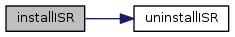
| void uninstallISR | ( | ) |
uninstall a previously installed interrupt handler
 1.8.11